|

Motor-Elektrik
Motor-Mechanik
|
|
moving
the water fan switch
in the
Gen I
of the years '99 - '07 |
Translated by help of "Google
Translater"
Hi dears,
since the
problem of, in the Gen I, over fee, say beyond the middle bar, rising
water temperature occurs again and again, I have written here once a
technical help.
Note :
With the Gen
II (from '08 onwards) no such conversion is necessary because there are
no fan switch in the cooler.
As the fan
switch in the Gen I sits in a seemingly unfavorable place in the
radiator and thus can not start the fan correctly, clever minds have
come up with a solution.
This is
simple :
Put the
switch in the right tube.
Thus, the fan
switch is always lapped by water and just can not detect anything wrong,
or he measures here the temperature that comes directly from the engine
and not only when the water, already a bit cooled down, at the old
measuring point, top left at the radiator, arrives.
The T-piece thus serves to
safely start the fan when reaching the switch-on point (according to
manual 105°C
/ 221 °F).
Due to this repositioning, the
fan gets its start signal earlier and starts earlier, which means that
even at 39°C / 102°F ambient temperature and heavy stop n'go the
display does not go beyond the middle line - so I have it in 2015 in a
brutal heat wave here in Berlin, Germany life experienced.
Here below a
little info
What,
Where
How
must be made.
It should be noted, however,
that the transfer of the fan switch one does not release it, when
changing the cooling water (X)
every 2 years (according to manual) correctly fill the radiator & vent,
as it by my brother is finest described on my homepage.
(X)
According to my personal assessment, a change of the cooling water at
the latest after 3 years should be just okay.
But then, I think, the old
broth is definitely due, because the glycol is subject to aging and
eventually loses its effect. (By the way, this also applies to our cars,
but in general nobody cares so much about that.)
One more thing :
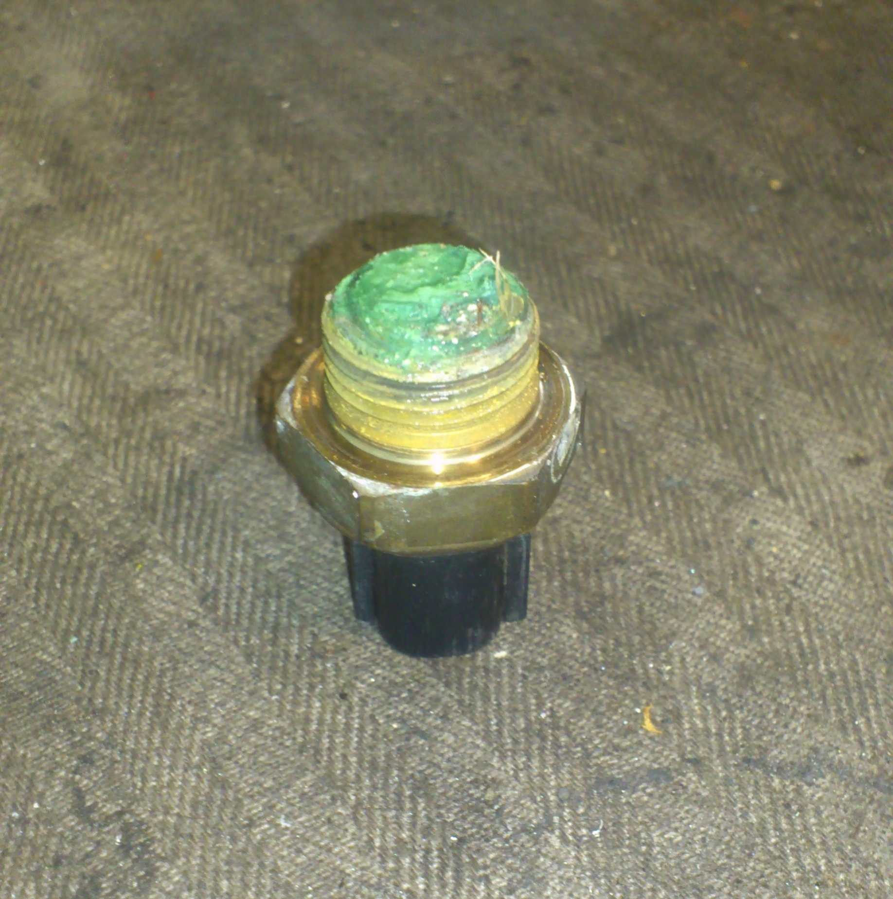
A. - Look
at the following two pictures and realize that at least the switch MUST
be out and cleaned every time when changing water!
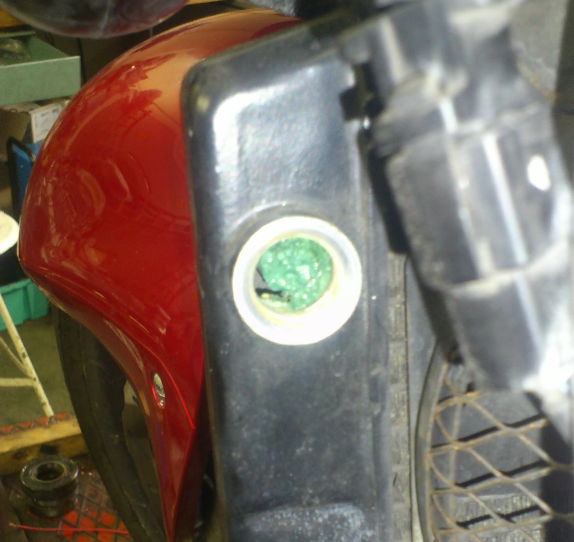
B. -
Something like that can be found if the cooling water was probably never
changed!
These two following pictures
are from a 99 Hayabusa.
My principle :
Who believes that the switch
in THIS condition can still measure properly, or a radiator can still
cool properly, certainly believes also in Santa Claus and Easter Bunny.

1 click on the picture & it
opens big in a new tab
|
gritty greenish green
mud on
the measuring surface
 |
gritty greenish green
Sludge
plug in the radiator
 |
|
NO wonder if the Busa blows the head gasket
at such a crap & maintenance backlog!
 |
Do not
start the work until the cooling water has cooled down sufficiently so
that you can loosen up the radiator. Otherwise threaten massive scalding!
|
the actual work
(out
of my sight)
: |
|
1. |
side covers both off |
|
2. |
tank up and remove the air filter box |
|
3. |
remove radiator cap and possible! remove
limescale even under the rubber seal |
|
4. |
empty the expansion tank, remove the retaining
screws and hang away the container |
|
5. |
pull off the coolant hose (left) on the water
pump and collect the broth |
|
6. |
pull off the coolant hose (right) on the radiator
and collect the broth |
|
7. |
remove plug from fan switch (Pic. 2) |
|
8. |
unscrew the fan switch (hex 24), clear the contact surface
with
fine
800 - 1,000 emery sand
of possible deposits and
screw it in the same way into the T-piece as the stopper (Fig.
2) and tighten to 17 Nm / 12.5 ft lbs
Now also screw the new plug (Pic. 6) into the thread of the
radiator - 17 Nm
/ 12.5 ft lbs |
|
9. |
cut the coolant hose on the right side (Fig. 1)
approx. 1 1/4" cm behind the protective hose and shorten the
hose leading to the cooler by approx. 1" |
|
10. |
mount the T-piece as shown in Pic. 1 / insert it into the hose &
gently! hand-tighten the 2 clamps (Pic. 7) - best - with a hex
ratchet 6 nut |
|
11. |
reassemble the hose on the radiator and fix it
with the hose clamp, but only gently! hand-tighten !
A hex 6 or 7
ratchet
nut, with a ¼ inch ratchet, is the best choice
here, a screwdriver the worst, because this is extremely the
risk of slipping. |
|
12. |
free the contact surface of the fan switch with
fine
800 - 1,000 emery sand from possible deposits (see above
gritty greenish green
..) |
|
13. |
screw in the fan switch (together with its seal)
into the T-piece, hex size 24, and tighten to 17 Nm
/ 12.5 ft lbs |
|
14. |
cut the wire of the fan switch about 10 cm / 4"
away from the plug (Fig. 3) |
|
15. |
plug
the switch into the new slot of the fan switch on the same (Fig.
4) and close the "gap" in the wire. The laying track is up to
you.
(I always put it through under the air filter box along the
overflow hose.)
If you want, you can make sure that the colors of the main wires
come together again, but not necessarily because the fan switch
is a pure I / O switch and thus when the 105°C / 221°F water
temp. just switch "on", let current flow, which makes the fan
work. |
|
16. |
reassemble
the hose on the water pump and fix it with the hose clamp, but
only gently! hand-tighten
(too much pressure is not created in the
cooling system - estimated around 1.1 - 1.15 bar / 15.9-16.7 psi (lb /
in²) |
|
17. |
reassemble the hose on the radiator and fix it
with the hose clamp (hex nut), that means gently! hand-tighten |
|
18. |
fill with new liquid
(XX)
and vent the radiator |
|
19. |
warm up engine and check for leaks at
a. the clamps on the T-piece
b. the clamp on the water pump
c. the clamp un the radiator
d. the Fan switch in the T-piece
e. the plug in the radiator |
|
20. |
air filter box back on it, gas-tank down and side
panels back to it |
|
|
aaaaaaaaaaaaaaand
 ready to ride
 |
|
|
|
|
What
you need on components : |
|
a. |
blanking plug (metric!)
M 18 x 1.5 with rubber O-ring seal (Pic. 6) (17 Nm / 12.5 ft lbs)
|
|
b. |
T-piece (picture 5) |
|
c. |
2 hose clamps
nominal size approx. 1 3/8" (~35 mm) - you
can get´em at the plumber |
|
d. |
(XX)
~ 170 cu in of cooling liquid - mixed 50:50 distilled water &
glycol
makes a anti-freeze
protection to at least -37 °C / -34 °F
only glycol which
is non-aggressive
against aluminum |
|
e. |
2 x approx. 1.0 m /
1 yd of wire with thickness 3/44" (0.75
mm²) its color does not matter |
|
f. |
shrink tubing or
insulating tape for solder joints |
|
|
|
|
|
|
By the
way:
The parts (as a
set), Figure 5. - 7. you can buy at
1.
Paul alias "Kojak" his Shop
for 62, - € + postage + import tax
payable via PayPal
2.
Bernd, alias "B-12" from the Hayabusa.de - Forum
and
3.
me (sometimes)
4.
from / at
Schnitz Racing USA
|
last
but not least :
Fill the old broth /
coolant into the empty containers and dispose of for disposal.
(at the seller? as is legal requirement in Germany?)
AND
Please
NEVER
pour the old broth / coolant into the environment or into the drain
anyway - the glycol itself (and also in any dilution) is basically
poisonous / toxic for all living beings and always harmful to the
environment.
a few explanatory pictures
1 click on the picture & it
opens big in a new tab
|
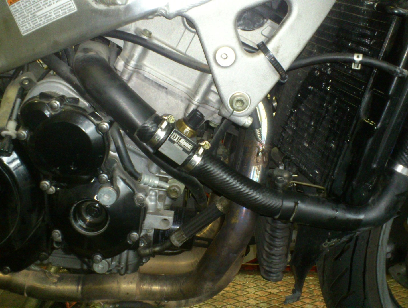
Pic. 1 - Installation location of the
T-piece
the original switch is
already screwed in
|
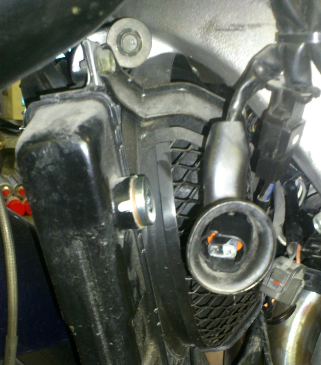
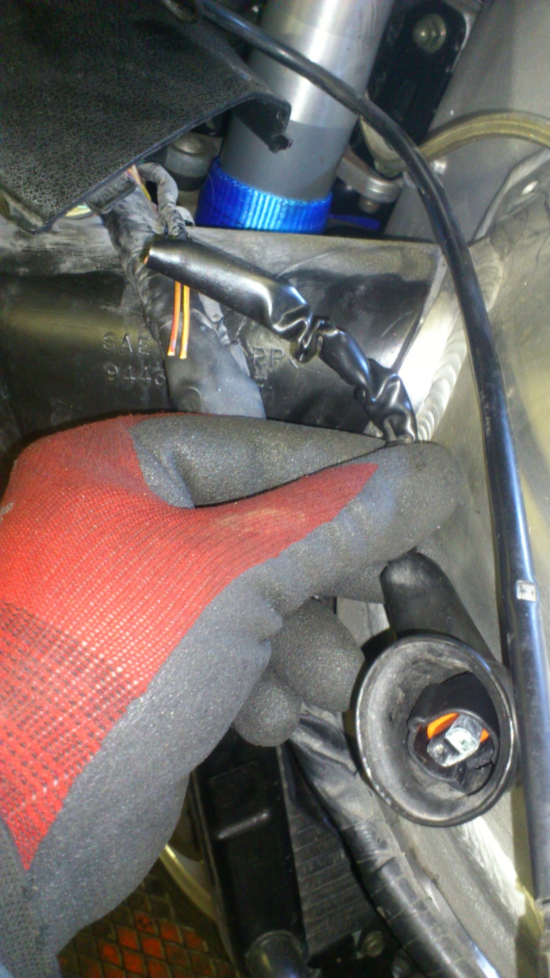
Pic. 2 - Switch connector
(blind-plug is already
screwed into the rad.)
 |
|
Pic. 3 - plug wire cut off
(main harness
left side / front, above the air duct)
 |
Pic.
4 - Connector plugged on switch
 |
|
|
|
|
Pic. 5 - T-piece (example)
inner thread M 18 x 1,5 (fan switch)
conn.-ends outer dia 26 mm (1 2/85")
 |
Pic. 6 - Plug M18 x 1.5 with 0-ring (example)
placed in radiator
here shown a hexagon head / Allen also possible
 |
|
Pic. 7 - Hose clamp (example)
dia
appr. 1 3/8" (&
~ 35 mm
 |
Hint :
Pic´s 5 – 7
illustration similar
|
That all the work is done with a cold
engine, I mention only as a matter of safety.
Not that afterwards one comes to me
with blisters and scalded hands and thinks he can demand compensation
for pain and so on.
Here, as with all descriptions of a
repair or conversion,
it is clear that :
EVERYONE
WORKS AT HIS OWN RISK !
and here
the whole "story" as a pdf to
Download
 |